
Prototype Update
The accessibility ramp will be deconstructed into its separate major components for testing purposes. Doing so will allow for more manageable testing on the somewhat large ramp. The majority of the weight the ramp will see while in use will be distributed to its legs. For that reason, a scaled prototype leg will be built in order to subject it to various loading conditions. This prototype will be built with the same material as the final design, 6061 aluminum. Also, a scaled model of an entire section of ramp will be 3D printed in its entirety out of plastic. This will allow for visual validation of dimensioning and functionality.

Figure 1: Leg Prototype
Leg Prototype
Figure 1 depicts a SolidWorks model of the scaled prototype leg. It consists of three components which are called out in the figure. Component 1 is the lower leg, which retracts into the upper leg (component 2). Component 3 is a square locking pin which will be used to fasten the upper and lower leg together. All of the materials required for this prototype have been purchased, received, and awaiting fabrication. This prototype will be used to test the following two conditions.
Weight
-
The scaled prototype of the leg will be subjected to a scaled force equivalent to the maximum load distributed to each full sized leg.
Processed Materials
-
The strength of the purchased 6061 aluminum tube and square locking pin will be stress tested to failure using a press.


Figure 2: Folded Section
Figure 3: 1/16" Scaled Prototype
Ramp Section Prototype
Figures 2 and 3 depict Solidworks models of the scaled sectional prototype. Figure 2 visualizes the foldability of the ramp, where the legs fold into the platform of the ramp, and the platform collapses into itself. Figure 3 is a representation of what each section of ramp will look like while unfolded and in use. Multiple sections will be combined to form a ramp of the desired application height. The drawings for the sectional prototype have been submitted and approved by the University at Buffalo Additive Manufacturing Lab, and printing will be completed by March 20th, 2017. This prototype will be used to test the following conditions.
System Envelope
The accurately scaled model of the ramp will be used to validate the dimensional requirements of the ramp.
Prototype Fabrication
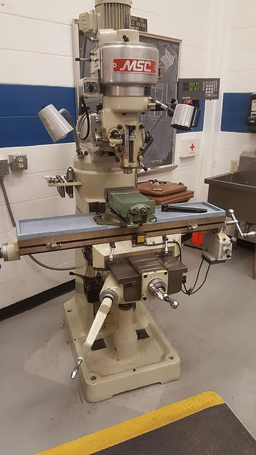
The prototypes were created at the University at Buffalo in the machine shop and additive manufacturing lab. All metal components were fabricated in the machine shop while all plastic components were fabricated in the additive manufacturing lab.
Bill of Materials

Equipment
Bandsaw
-
The bandsaw was used to cut the raw materials to length. The components were cut slightly long and then were ground down to the correct dimensions. The band saw was used for items 4 and 5 of the 1/6th scale prototype.

End Mill
-
The end mill was used to drill holes in the leg components for both the full-scale prototype and the 1/6th scale prototype. The end mill was used for items 4 and 5 of the 1/6th scale prototype as well as items 1 and 2 of the full-scale leg prototype.
Grinder
-
The grinder was used to adjust the dimensions of the components cut on the band saw. The components were cut slightly longer than desired so that they could be ground down to exactly the right dimension. The grinder was also used to add fillets to the tops of the legs on the 1/6th scale prototype. The grinder was used for item 4 of the 1/6th scale prototype.

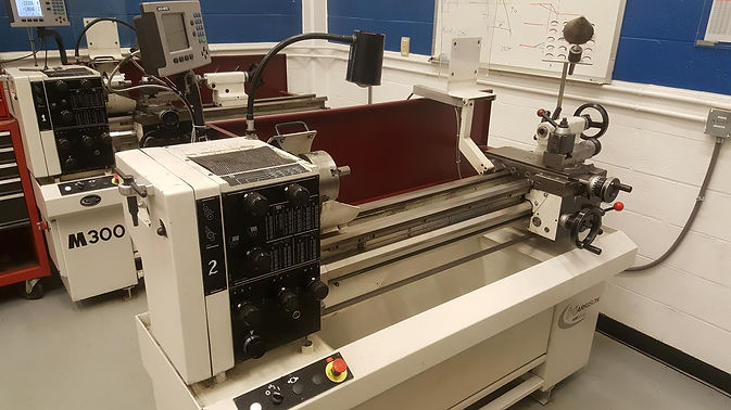
Lathe
-
The lathe was used to bore out the large tubing for the full-scale leg prototype. The tolerances of the ordered tubing ended up overlapping so they didn't fit together. A small amount of material was removed from the inside of the large tube so that the smaller tube would fit inside correctly. The lathe was used for items 1 and 2 of the full-scale leg prototype.
Makerbot Replicator 3D Printer
-
The MakerBot was used to make all of the plastic (PLA) components in the 1/6th scale prototype. These include items 1, 2, 6, 7, and 9.

Makerbot Replicator 3D Printer
-
The MakerBot was used to make all of the plastic (PLA) components in the 1/6th scale prototype. These include items 1, 2, 6, 7, and 9.
Prototype progress
-
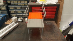
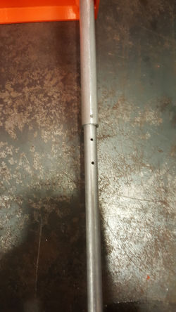
Both the full-scale leg prototype and the 1/6th scale full section prototype have been fabricated and tested. Please see the gallery below to view a gallery of images of both the full-scale prototype and untested leg prototype.
 |  |
|---|---|
 |  |
 |  |
 |  |
 |  |
 |  |
 |  |
 |  |
 |  |
 |
Leg Prototype Testing and Validation
The leg prototype was tested in a hydraulic press. The press was programmed to compress the prototype one inch over the course of one minute. As predicted, the steel pin sheared through both the upper and lower leg. The images below show the testing conditions along with the prototype after deformation. Also included is a video of the entire test.
![DSC_0639[1]](https://static.wixstatic.com/media/2e8e75_ff223d24f19c4414b2b8ae4659439586~mv2_d_4481_3991_s_4_2.jpg/v1/fill/w_250,h_222,al_c,q_90,enc_auto/2e8e75_ff223d24f19c4414b2b8ae4659439586~mv2_d_4481_3991_s_4_2.jpg) | ![DSC_0638[1]](https://static.wixstatic.com/media/2e8e75_3fb1ede416c5419b96b098f0ee54df37~mv2_d_1761_3759_s_2.jpg/v1/fill/w_250,h_533,al_c,q_90,enc_auto/2e8e75_3fb1ede416c5419b96b098f0ee54df37~mv2_d_1761_3759_s_2.jpg) |
|---|---|
 |  |
The test yielded a force curve for the ramp as shown on right. The ultimate force of the leg was 7900 lbf. The force the leg withstood before plastically deforming was 5200 lbf. The results of this test are well within the expected results calculated through FEA and hand calculations. Based on these three modes of evaluation, these results are well beyond the maximum force each leg will be subjected to throughout its life cycle, and the design of the ramp is acceptable for human use.
